Vehicle impaired when UltraGauge is attached
Examples of impairment are the traction control or other dash indicators may become lit, or the speedometer or other gauges may temporarily stop functioning, or the check engine light may become lit. There are two scenarios that may cause this issue:
Scenario 1
When the ignition is switched on the ECU may perform a self test. During this self-test if UltraGauge issues a request to the ECU, the ECU may consider it a self-test fail, and light various warning lights on the dash. With the UG default Power On Detect Mode settings, UG will not wake up until the vehicle is started; hence UG will not make a request until after the vehicle is running. For 99.9% of vehicles there is no issue. However, for some with a long self test or slow ECUs, or one that places the OBDII test at the end of the self test, it maybe necessary to switch the ignition to the run position and then wait for self test to complete before starting the vehicle. How long should you wait? This will depend on the self test and ECU. 5 seconds should be a good starting point if you experience this issue.
Scenario 2
This issue, although rare, was associated with the transition by manufacturers from older protocols to the new CAN protocol prior to 2008. This has been seen on some 2005 to 2007 vehicles. All 2008 and newer USA vehicles use the CAN protocol and this is no longer an issue. This issue is the result of manufacturers not strictly following the the OBDII standard.
When UltraGauge is attached to the OBDII connector it begins scanning for one of five possible interfaces/protocols. Once the interface is determined, UltraGauge then discovers the available gauges
During the scanning phase, UltraGauge tries each of the electrical interfaces/protocols associated with the OBDII standard. Depending on the interface, different pins of the OBDII connector are used:
| Interface | Connector Pins |
| J1850-VPM | 2 |
| Early Ford | 2,10 |
| ISO 9141 | 7,15 |
| CAN | 6,14 |
| KWP2000 | 7,15 |
| Common pins: | |
| Battery | 16 |
| Ground | 5,4 |
Vehicle's female OBDII connector: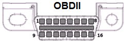
The issue is that manufacturers improperly use pins that they should not. For example, a 1999 Ford would use pins 2,10,16,4 & 5. If Ford then used any of the other pins defined above, say pin 7 & 15, the stage is set for a potential issue.
During the scanning phase UltraGauge will try each of the interfaces. Returning to our example. While Scanning our 1999 Ford, UltraGauge will drive pins 7 & 15 in an attempt to determine if the vehicle is ISO 9141. Since the vehicle is a Ford, no communication will be established and UltraGauge will try the next interface. If however, the manufacturer has used pins 7 & 15 for proprietary uses, the vehicle may become impaired. For example, on some vehicles the traction control light may become lit, or the speedometer or other gauges may temporarily stop functioning, or the check engine light may become lit. To avoid these issues, the Protocol & Interface can be fixed to that used by the vehicle. Please see the "Force Protocol" section of the users manual. When the protocol is forced, UltraGauge will only try the set protocol. In the case of our 1999 Ford, UltraGauge will only drive pins 2 and 10, and will no longer attempt to drive pins 7 & 15. However, the vehicle's ignition should be switched off, then on after this setting is made, to reset any impairment.
What if "Force Protocol" does not resolve the issue?
It then becomes necessary to find and isolate the offending pins. If when looking into the vehicle's OBDII connector there are pins present beyond those used for your vehicle's protocol and there is a corresponding pin on the UltraGauge connector, isolate the pin(s) until the problem is resolved.
See the following similar knowledgebase article
9141 & KWP2000 Isolation Cable
If your UltraGauge has been working fine, and now after some time is impairing the vehicle, please try issuing the equivalent of a reset. The following procedure is much different than unplugging and plugging an UltraGauge. This procedure will restore UltraGauge back to factory defaults, erasing all previous configuration changes.
Restoring an UltraGauge (Wired Version):
1. Unplug UltraGauge
2. Set the ignition to the RUN position
3. Press and hold the MENU key.
4. Plug in UltraGauge.
5. Wait 5 seconds, Release the MENU key. The MENU system will start.
6. Select MENU --> UltraGauge Setup.. --> Restore ALL Defaults.
You will then be prompted to confirm. Once confirmed UltraGauge will reboot and begin Scanning for the interface and protocol used. Once found UltraGauge will begin Gauge discovery.
Restoring an UltraGauge Blue (Wireless Version):
1. Unplug the UltraGauge Blue Adapter
2. Set the ignition to the RUN position
3. Press and hold the button on the Blue Adapter while plugging it back in
4. Go to the UltraGauge Blue App and wait for it to connect (once connected, you should see a "down arrow" near the top left corner where the Bluetooth icon normally appears. This means the Adapter is in Update mode).
5. Go to the Settings->UltraGauge Settings->Update Blue Adapter screen.
6. Make sure the 'Factory Default Blue Configuration" box is checked on this screen and click "Next". Follow the prompts to complete the Update. This will make sure that the correct Version of the Adapter is installed and will also restore the configuration on the Adapter.
Once completed, UltraGauge will reboot and begin Scanning for the interface and protocol used. Once found UltraGauge will begin Gauge discovery.
The down side of a global reset is that it will erase any configuration and calibration previously performed.